Quantcast
Channel: My Commentary and Technical help
Viewing all 306 articles
Browse latest View live

More problems and another solution to the Head Gasket Problem with Bar's Leaks Professional.

$
0
0
My HHR overheated again only two months after the last time that I tried to fix it.  The radiator was down two quarts of fluid.  This time I decided to spend some more money and get something that stays in the radiator.  It is called "Bar's Leaks Professional", and runs about $45.

Its only been a few days but so far so good.  I might have to change the oil once again. It looks a little brown.  There was no foam on the oil fill cap this time.

Better to sell using Auctions instead of fixed price on eBay!

$
0
0
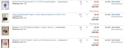
A while back eBay offered me a deal on fixed price 30 day listings, they were free.  I always look at the "buy it now" prices because I do not want to wait for an auction.  On top of that auction listings are 30 cents each so it made sense to switch, right?  Wrong!  My sales tanked.  So I have gone back to auctions.  First here is a picture of my 30 day listings after 15 or more days with typically 10-20 views over that time.

Now compare that to some auctions that are only 1 day old with 60-150 views per 24 hours!
So forget about the 30 day fixed price listings they are free but a total waste of time!

Big Audio Spectrum Analyzer with Arduino UNO+MSGEQ7+WS2812 LED Strips

$
0
0
I have finally been able to get the combination of a MSGEQ7 and WS2812 LED strips to work together.  The trick was to not use any machine language code.  Instead, to access the WS2812 I just used parallel output commands like this:
  PORTD= 0xFF;  // turn on
  PORTD= 0xFF;  // delay
  PORTD= 0xFF;  // delay (Remove for faster processors)
  PORTD= bits;  // send data
  PORTD= bits;  // delay
  PORTD= bits;  // delay
  PORTD= bits;  // delay
  PORTD= bits;  // delay
  PORTD= 0x00;  // Turn off;
Sending the same command over and over just results in a delay.

This setup gives 90 steps to the top.  I am missing one LED strip for the needed total of 14.  I will add three more strips as soon as they arrive from China.

Here are some links to the videos on YouTube.  For some reason they don't embed the videos like they used to?  I think they are working now.


This is the code for the right channel only, but blogspot might remove all of the < and > from the code.....

// BOB Davis Enhanced Version for sending data to 8 Parallel WS2812 strings
// Removed Assembler and simplified the code
// Changed to VU meter with MSGEQ7

// PORTD is Digital Pins 0-7 on the Uno change for other boards.
#define PIXEL_PORT  PORTD  // Port of the pin the pixels are connected to
#define PIXEL_DDR   DDRD   // Port of the pin the pixels are connected to

// MSGEQ7 pins
#define PIN_STROBE 9
#define PIN_RESET 10
#define PIN_LEFT 4 //analog input
#define PIN_RIGHT 5 //analog input

//band arrays
int left[7];
int right[7];
int col=0;

void readMSGEQ7() { //reset the chip
  digitalWrite(PIN_RESET, HIGH);
  digitalWrite(PIN_RESET, LOW);
  for(int band=0; band < 7; band++) {  //loop thru all 7 bands
    digitalWrite(PIN_STROBE,LOW);      // go to the next band
    delayMicroseconds(30);             // gather data
    left[band] = analogRead(PIN_LEFT); // store left band reading
    right[band] = analogRead(PIN_RIGHT); // store right band reading
    digitalWrite(PIN_STROBE,HIGH);     // reset the strobe pin
  }
}

// Actually send the next set of 8 WS2812B encoded bits to the 8 pins.
// The delay timing is for an Arduino UNO.
void sendBitX8( uint8_t bits ) {
  PORTD= 0xFF;  // turn on
  PORTD= 0xFF;  // delay
  PORTD= 0xFF;  // delay (Remove for faster processors)
  PORTD= bits;  // send data
  PORTD= bits;  // delay
  PORTD= bits;  // delay
  PORTD= bits;  // delay
  PORTD= bits;  // delay
  PORTD= bits;  // delay
  PORTD= 0x00;  // Turn off;
}

// Set default color for letters
int red=1;
int green=1;
int blue=1;

void sendPixelRow( uint8_t row ) {
  // Send the bit 8 times down every row, each pixel is 8 bits each for R,G,B
    for (int bit=0; bit <8; bit++){     
      if (green==1)sendBitX8( row );
      else sendBitX8( 0x00 ); }
    for (int bit=0; bit <8; bit++){     
      if (red==1)sendBitX8( row );
      else sendBitX8( 0x00 ); }
    for (int bit=0; bit <8; bit++){     
      if (blue==1)sendBitX8( row );
      else sendBitX8( 0x00 ); }
 }
void setup() {
  PIXEL_DDR = 0xff;    // Set all row pins to output
  pinMode(PIN_RESET, OUTPUT); // reset
  pinMode(PIN_STROBE, OUTPUT); // strobe
}
void loop() {
  red=0;
  green=1;
  blue=0;
    readMSGEQ7();                   // collect samples
    cli();                          // No time for interruptions!
    for (int b=1; b > 90; b++){
      if (b > 60) {red=1; green=0;}
      else       {red=0; green=1;}
      col=0;
      if (right[0]-64 >= b) col=col+1;  // Send bytes as VU meter data
      if (right[1]-64 >= b) col=col+2;  // Send bytes as VU meter data
      if (right[2]-64 >= b) col=col+4;  // Send bytes as VU meter data
      if (right[3]-64 >= b) col=col+8;  // Send bytes as VU meter data
      if (right[4]-64 >= b) col=col+16;  // Send bytes as VU meter data
      if (right[5]-64 >= b) col=col+32;  // Send bytes as VU meter data
      if (right[6]-64 >= b) col=col+64;  // Send bytes as VU meter data
      sendPixelRow(col);
      }
    sei();                        // interrupts back on
    delay (50);
//  }
}
90>8>8>8>

SainSmart DDS120/DDS140 USB DSO Oscilloscope

$
0
0
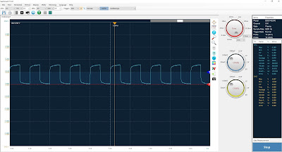
I just purchased a SainSmart DDS140 DSO on eBay. So far I have figured out how to get a trace on the screen using the built in signal generator.  Who puts the "Start" button in the bottom right corner?  Next is to test it in some real world situations like my WS2812 LED strip signs.

Assembling the Chinese RTL-SDR Kit (Software Defined Radio)

$
0
0
I am building a Chinese RTL-SDR Kit.  To start with I was trained in soldering by MERP (Miniature Electronics Repair) school in the US Navy.  I was taught NASA standards for soldering.  They will surely disown me after seeing these pictures of my soldering. This kit is NOT easy!  I also work for a communications company.  I have built all kinds of communications equipment including surface mounted parts and hand wound coils.

Here is what the kit parts look like.  There are many really tiny parts in the parts bag!

The circuit board comes with none of the surface mount parts installed.

To solder the surface mounted parts you will need a magnifying headband visor.  You will also need tweezers and a really fine soldering tip. Apply a small amount of solder to one pad and place one end of the part in the molten solder.  Then solder the other end.  Then clean up the first side.  The surface mount parts are marked except for the 222 resistors, the LED and the 4.7uH choke.  The LED is in a black part holder and has a green stripe.  There are extras of some parts in case you loose some.


Here is a picture of the circuit board with the surface mounted parts jacks, and capacitors added.  The green stripe of the LED goes towards the USB jack.  The USB Jack is really hard to solder.  I ended up with a solder bridge.  After trying every trick to get rid of the bridge I resorted to using solder wick to soak up the extra solder.  The capacitors should have their ground stripes facing the outer edges of the board.

I skipped adding the coils and went right to the disassembling USB dongle.  Use solder wick to remove the solder on the ground connections.  Then clip off the four USB jack pins using flush cutters.  Then clear the metal out of the holes with a solder sucker. (Or heat and tap).

To add the USB assembly make two jumper hooks out of the former capacitor wires.  Use them to hold the USB assembly up as in the following picture.  Then solder them in place on both the top and bottom sides.

Next make a |_____| to connect the bottom grounds together as in the next picture.
Then add the four USB jumpers (from the old jack to the new jack) two ground jumpers, and RF input jumper on the top side of the board.

More Arduino Uno With WS2812 LED Strips and Arrays

$
0
0
I have been continuing to do things with an Arduino UNO and addressable LED's.  I think my next book will be called "Arduino Addressable LED Projects".  I would prefer to keep the title to three words and "Addressable" is a long word.

Currently I am experimenting with an 8x32 array.  Internally it is wired as 8 LED segments with a zigzag wiring so each column is reversed.

Here is my worm video that shows how it is wired internally:

Here is some text being displayed on it.

I have improved the software even more!  It now supports 256 shades of each color and a color for each letter.

Even More Arduino Uno With WS2812 LED Strips and Arrays

$
0
0
I have also made a larger higher density LED sign.  It features 90 LED's per row and 16 columns.  That is 1440 LED's.  It is running from an Arduino UNO.  Last night with some adjustments to the timing I was able to get it to work.

The software now supports a different color for each letter as in this picture.

Here is the shades of color test, it supports 256 shades of each color.

Here is a video of it displaying text and running the color test and fireworks effect.

Audio Spectrum Analyzer with Arduino UNO+MSGEQ7+WS2812 LED Strips Part 2

$
0
0
I have improved the Audio Spectrum Analyzer.  By increasing the number of MSGEQ7's and offsetting them I now have 21 frequencies per channel.  In order to display all of them the sign had to be turned sideways.

This first version supports 8 LED strips:


This second version supports two sets of 8 LED strips for a total of 16 strips.


I can even do an oscilloscope on the WS2812 LED sign.


Arduino WS2812 144 LED per Meter sign

$
0
0
I am building a third sign that has 144LED per meter or 1/4 inch LED spacing.  The first tests indicate lots of bad connections.  The issue is likely in the LED strips being shipped wrapped on a spool that is too small.

In this first picture the middle row quits about 3/4 the way across the sign.  One of the pixels in the "U" is red but that is hard to tell in the picture.

In this next picture the bottom right corner LED is out.  The third row down is a different shade of blue but you cannot see that in the picture.

here is the video of the first test.  Some of the issues went away during the video indicating they are caused by bad connections.


Chevy HHR Failure to Start or Start then Stall Problem

$
0
0
This fall my HHR started having issues with starting.  By Christmas time it no longer started.  At one point I spent over 30 minutes trying to start it.  When it started there was a multicolored puddle of gas under the tailpipe.  It always smelled of too much gas.  I changed the spark plugs and the old plugs were covered in black from too much gas.

The HHR would sometimes start, and if I pumped the gas it would eventually sustain.  Eventually I discovered that if I floored the gas pedal before starting it it would usually start.  Through research I discovered that flooring the gas pedal should shut off all gas to the motor!  Eventually the check engine light came on.  Here are the codes and what they meant.

The codes are:
P0300 Engine Misfire Detected
P0107 Manifold Absolute Pressure (MAP) Sensor
P0122/P0123/P0223 Throttle Position (TP) Sensor.
P0171 System too Lean

The auto store wanted over $250 in parts.  I bought the MAP sensor on eBay for $10 and the Throttle body form the 1490 motors (an auto salvage place) for $40.  The exact same codes came back on again.  I was getting really frustrated.  Then I got thinking, how could so many sensors be so wrong?  So I decided to replace the motor ground wire.  When I looked at the old wire one end seemed loose.  I puled on it and the wire came right out!  After close examination I determined that the wire was never crimped into the connector.


Here is the new crimped and soldered triple ground wire.  It runs from the right side of the motor to the right strut tower.


This is a close up of the bolt on the cam cover that the ground wire is connected to.


Now I just touch the key for a fraction of a second and the car starts right up!


Interactive Arduino Uno Ethernet Shield Program

$
0
0
I have developed a Interactive Arduino UNO Ethernet Shield demo program.  It requires lots of memory.  It was a offshoot while I was developing a Ethernet based method of updating my LED signs. However the UNO suffers from a memory shortage just running this demo program!  This is what the screen looks like.  You cannot change D10-D13 because they are used by the Ethernet card.


I have finally found an easy way to post code on blogger!  Thanks to "http://codeformatter.blogspot.com/" the code can be easily formatted.

 // Arduino Ethernet Interactive with table  
// By bob Davis
// Based on code from Rui Santos

#include <Ethernet.h>
int led1 = 2;
int led2 = 3;
int led3 = 4;
int led4 = 5;
int led5 = 6;
int led6 = 7;
int din1 = 8;
int din2 = 9;
int din3 = 10;
int din4 = 11;
int din5 = 12;
int din6 = 13;
int data1 = 0;
byte mac[] = { 0xDE, 0xAD, 0xBE, 0xEF, 0xFE, 0xED }; //physical mac address
byte ip[] = { 192, 168, 1, 21 }; // ip in network
EthernetServer server(80); //server port
String readString;
void setup() {
// Open serial communications and wait for port to open:
pinMode(led1, OUTPUT);
pinMode(led2, OUTPUT);
pinMode(led3, OUTPUT);
pinMode(led4, OUTPUT);
pinMode(led5, OUTPUT);
pinMode(led6, OUTPUT);
pinMode(din1, INPUT);
pinMode(din2, INPUT);
// start the Ethernet connection and the server:
Ethernet.begin(mac, ip);
server.begin();
}
void loop() {
// Create a client connection
EthernetClient client = server.available();
if (client) {
while (client.connected()) {
if (client.available()) {
char c = client.read();
//read char by char HTTP request
if (readString.length() < 100) {
//store characters to string
readString += c;
} //if HTTP request has ended
if (c == '\n') {
client.println("HTTP/1.1 200 OK"); //send new page
client.println("Content-Type: text/html");
client.println("Refresh: 2"); // refresh every second
client.println();
client.println("<HTML><BODY>");
client.println("<style>table, th, td {padding: 3px; border: 1px solid black;</style>");
client.println("<table width=350><tr>");
client.println("<th colspan=6>Digital Outputs</th>");
client.println("</tr><tr>");
client.println("<th>D2</th><th>D3</th>");
client.println("<th>D4</th><th>D5</th>");
client.println("<th>D6</th><th>D7</th>");
client.println("</tr><tr>");
client.println("<td><a href=\"/?button1on\"\">Turn On</a></td>");
client.println("<td><a href=\"/?button2on\"\">Turn On</a></td>");
client.println("<td><a href=\"/?button3on\"\">Turn On</a></td>");
client.println("<td><a href=\"/?button4on\"\">Turn On</a></td>");
client.println("<td><a href=\"/?button5on\"\">Turn On</a></td>");
client.println("<td><a href=\"/?button6on\"\">Turn On</a></td>");
client.println("</tr><tr>");
client.println("<td><a href=\"/?button1off\"\">Turn Off</a></td>");
client.println("<td><a href=\"/?button2off\"\">Turn Off</a></td>");
client.println("<td><a href=\"/?button3off\"\">Turn Off</a></td>");
client.println("<td><a href=\"/?button4off\"\">Turn Off</a></td>");
client.println("<td><a href=\"/?button5off\"\">Turn Off</a></td>");
client.println("<td><a href=\"/?button6off\"\">Turn Off</a></td>");
client.println("</tr><tr>");
client.println("<th colspan=6>Digital Inputs</th>");
client.println("</tr><tr>");
client.println("<th>D8</th><th>D9</th>");
client.println("<th>D10</th><th>D11</th>");
client.println("<th>D12</th><th>D13</th>");
client.println("</tr><tr>");
client.println("<td align='center'>");
data1=digitalRead(din1);
client.println(data1);
client.println("</td>");
client.println("<td align='center'>");
data1=digitalRead(din2);
client.println(data1);
client.println("</td>");
client.println("</tr><tr>");
client.println("<th colspan=6>Analog Inputs</th>");
client.println("</tr><tr>");
client.println("<th>A0</th><th>A1</th>");
client.println("<th>A2</th><th>A3</th>");
client.println("<th>A4</th><th>A5</th>");
client.println("</tr><tr>");
for (int aChannel = 0; aChannel < 6; aChannel++) {
int sensorReading = analogRead(aChannel);
client.println("<td align='center'> ");
client.println(sensorReading);
client.println("</td>");
}
client.println("</table></BODY></HTML>");
delay(1);
//stopping client
client.stop();
//controls the Arduino if you press the buttons
if (readString.indexOf("?button1on") >0){ digitalWrite(led1, HIGH); }
if (readString.indexOf("?button1off") >0){ digitalWrite(led1, LOW); }
if (readString.indexOf("?button2on") >0){ digitalWrite(led2, HIGH); }
if (readString.indexOf("?button2off") >0){ digitalWrite(led2, LOW); }
if (readString.indexOf("?button3on") >0){ digitalWrite(led3, HIGH); }
if (readString.indexOf("?button3off") >0){ digitalWrite(led3, LOW); }
if (readString.indexOf("?button4on") >0){ digitalWrite(led4, HIGH); }
if (readString.indexOf("?button4off") >0){ digitalWrite(led4, LOW); }
if (readString.indexOf("?button5on") >0){ digitalWrite(led5, HIGH); }
if (readString.indexOf("?button5off") >0){ digitalWrite(led5, LOW); }
if (readString.indexOf("?button6on") >0){ digitalWrite(led6, HIGH); }
if (readString.indexOf("?button6off") >0){ digitalWrite(led6, LOW); }
//clearing string for next read
readString="";
}
}
}
}
}

Arduino UNO Running 12 WS2812 LED Strips with a BIGGER Font

$
0
0
I have modified my LED sign setup once again.  I now have an Arduino UNO Running 12 WS2812 LED Strips with a BIGGER Font.  The 12x8 font had to be typed in manually as I could not find one that suited me.  To get 12 lines running from a UNO I used both the "B" and "D" ports or D0 to D11 data pins.  The uppercase fonts only use 10X8 as the lower two rows are for lower case letters that extend below the line.

This is what the sign looks like in multi-color mode.

Here is the Video:


I can also do graphics on the LED sign.  This is a picture of the logo that I uploaded as a BMP to the sign for display.  I was looking for something with lots of color and with a black background.  White backgrounds do not work very well as the white light blinds you!  To display graphics I had to write a routine to rotate the bytes from horizontal to vertical orientation.  Then I added an offset to make it scroll up.  I should mention that this is running in 8 data line mode, the right side loops back to the next 8 rows on the left side to get up to 16 lines to display.


This is the video on YouTube.


Here are a couple of still shots of the sign displaying graphics.


Devastator Tank Mobile Robot Platform for Arduino or Raspberry Pi

$
0
0
I am building a "Devastator Tank Mobile Robot Platform" kit from dfrobot.  I bought it through robotshop_inc on eBay.  The hardware took only one hour to assemble.  The manual has lots of pictures to make assembling it easy.  Each type of screw has a bag with its part number on it.  The only tool I wish I had is the tiny wrench for the lock nuts.  You can use needle nose pliers but a wrench would be much easier to use.


Now for the electronics.  Stay tuned......


Dream Cheeky USB Nerf Missile Launcher to Arduino with Bluetooth and Android

$
0
0
I recently purchased two defective Dream Cheeky USB Foam Missile Launchers.  I wanted to add one to my Devastator tank (See other blog posts).  So far I have rebuilt one of them.  The turret did not rotate and it did not fire correctly.  The other one only fires from one position and the turret does not move up and down.

There are two USB missile launcher designs.  One has a rotating missile holder for four missiles.  The other design holds three missiles and fires them without rotating.

On the first USB launcher the rotation issue worked when I connected a battery to the motor so the issue was in the electronics.  The firing issue was related to some teeth missing form a gear.  I fixed that by re-positioning the gear.  Note that to dissemble the top assembly there are two screws on the left side, one is hidden behind some green tape and the other is only half hidden behind the tape.

Here is a picture of all of the guts opened up except for the top.

Here is the wiring color code.  Note that there are several wires having the same color as other wires.

Launcher wiring color codes:

Top Part:
Fire motor; Red, Orange (red is +)
Fire switch; Green, Green

Bottom Assembly:
Rotate motor; Yellow, Green
Rotate Switch; 2x Yellow, 2x Orange
Height Motor; White, Blue
Height switch; Black, Red, Brown

Next I will connect a motor controller and an Arduino to obtain working serial control of the launcher.  I used a L298 motor control for the turret and a TIP120 for the fire function.  The USB power was not sufficient for the fire motor so I used a 9V battery.

Here is the first test video.  I need to get the right kind of missiles!


Air Hogs battle Tracker Hacked

$
0
0
I bought an Air Hogs "Battle Tracker" Nerf Missile launcher hoping to put on my Devastator tank.  It is obviously way too big for that!  However I still hope to interface it to an Arduino or Raspberry Pi and add the ability to track targets perhaps by Infrared.


The wired interface appears to be a voltage divider so each button returns a voltage.

Audio Centron RMA-1600 Audio Amplifier rebuild

$
0
0
I have been rebuilding aa Audio Centron power amplifier.  The TO-3 transistors were bad and it was cheaper to replace all of the "guts".  The power supply is positive and negative 80 volts.  So I searched eBay for a amplifier board that can handle that voltage.  This is what I found:

1PC NJW0281/NJW0302 450W+450W HIFI Stereo Amplifier Board Assembled AMP Board

Description :

This is completed board.You don't need solder it.
4 Pair MJW0281/MJW0203 for one channel.
so one board has 1 6pcs transistors.
Power supply: DC 45V to 85V
Power: 2X450W (-85V @ 4 Ohms)
PCB size: 259 * 73MM

However if I was to do it over I would use a PR-800 amplifier board.

Here are some picture of the amplifier rebuild.  We used an old heatsink and tapped the necessary holes in it.  The heatsink is upside down while we connect the wires to it.  The power and speaker posts fit the connector pins from an ATX power supply.


Ford Taurus Passenger Blend Door Actuator

$
0
0
My wife's car had the heat stuck on for the passenger side only.  It was way too hot and it would not turn down.  The problem was a motorized door that was stuck.

Here is an excellent video on how to change the actuator.

I used my fingers to disconnect the electrical connector and that might be easier to do before the actuator is removed.  It is identical to the other connector to the right so you can see what your are feeling for.  Basically you push in a small tab in the center and pull up on the wires.

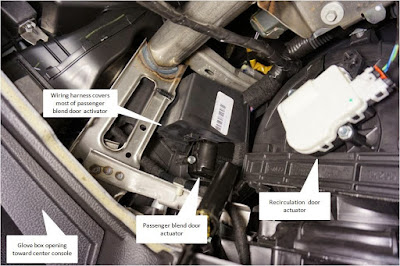
Here is an great picture of what to look for behind the glove box.

Source: http://www.taurusclub.com/forum/114-5th-6th-gen-maintenance-repair/244434-driver-side-blows-cold-passenger-side-blows-hot.html

This is how to test the heating and cooling system.
Turn the heating/cooling system off before you start.

The self-test can be initiated after cycling the ignition switch from OFF to ON.
For the self-test, press the OFF and DEFROST buttons together and release them.
Then press the AUTO button - ALL within 2 seconds.
The display will show a moving bar-graph icon for 20 seconds.
If diagnostic codes are present, they will be displayed.
My codes were "12 42" and "22 67"
When done press any button to exit.
Wait 30 seconds to turn the key off for the computer to re-calibrate.

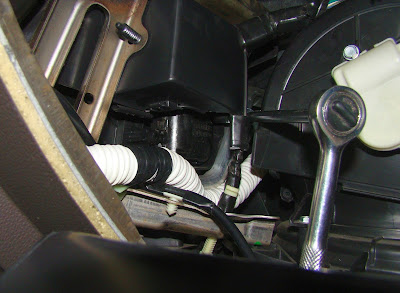
Here is a picture looking into the glove box area.

This picture is going in a little closer.  I moved the white wire harness down out of the way.

Here is the tool setup I used to get to the back screw.  I had to purchase a 1/4 inch universal joint for $5 that you cannot see in the picture.

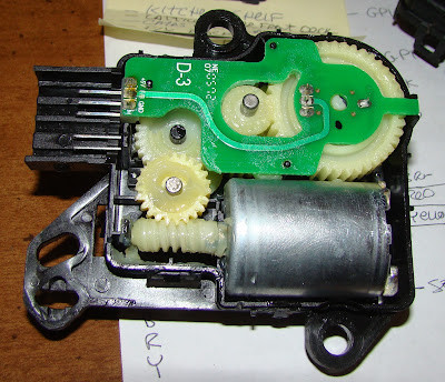
Here is what is inside of the actuator.  You can test the motor with a 9 volt battery.  The two connections to the motor are on the right side (back) of the motor.  My motor turned a couple of times and stopped.  I thought maybe the mechanics were stopping it, but no it was the motor itself.


Rebuilding LAB Series LS800 Amplifier with a L-15 Amplifier

$
0
0
I am rebuilding another power amplifier.  This time I chose the L-15 amplifier because it fits in the heatsink.

The L 15 amplifier compared to the old circuit board for size.
 The amplifier totally dissembled into pieces.
 The back panel of the amplifier.
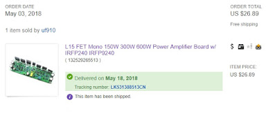
Here is the ebay ad for the replacement amplifier.
The L15 fits nicely in the heat sink
I am using 4 pin power connectors for 5.25 floppy drives for power and ground.


Niles ZR 4630 tear down and rebuild

$
0
0
A friend has a Niles ZR-4630 that he wants made into independent amplifiers.  There are six stereo amplifiers based on the LM3886 IC.  I have been reverse engineering it.  By default the mute is "on" for the amplifier modules.  Here are some pictures of the guts.
This shows the amplifier modules and the power transformer.  We could not get the power on by the on off switch so we hot wired power to the transformer.
This is another view of the transformer and amplifiers.
This is a view of the back side of the guts.
So far I have been able to confirm the pins of the amplifiers. There is more to come.

2018 Chaffee NY Hamfest

$
0
0
I was at the 2018 Chaffee NY Hamfest.  It is a smaller one but I got some great deals. This is what it looked like.
Here is my table.  I failed to get rid of my free stuff!
I bought a metal locator and some speakers.  Here are the speakers that I will use to rebuild my speakers with.
Viewing all 306 articles
Browse latest View live